

UCA Sizing Procedure
Background
The following procedure outlines the process for installing bushings and sizing the pivot.
Special Tools
1. Milling Machine with 1/2 or larger end mill
2. Expandable Reamer
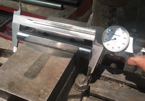
3. 12” Calipers
4. Hydraulic press or large vise
Bushing Installation Procedure
1. Press Bushings – Press the new bushings into both ends of the UCA (Upper Control Arm). Be sure they are pressed all the way in.
2. Check Pivot Fit – Try pressing in the pivot by hand. If you can get it into place by hand it will probably require sizing. The pivot should be a tight non-press fit.
3. Ream Bushings – If the fit is to tight, use an adjustable reamer to open up the inner diameter of the bushings a little at a time until the pivot shaft goes through without force. If you don’t have a reamer a piece of sandpaper wrapped around a 3/4” rod will work.

4. Square off Ends – The bushings might not be orthogonal with the axis of the pivot and should be checked. If the end of the bushing is not normal with the axis, they should be milled. Install a 1” shaft into the mill vise, slip the UCA onto the shaft, and then mill just enough of the end to make it normal to the pivot. If you don’t have a mill, a disk sander can be used.

Pivot Sizing Procedure
5. Measure UCA and Pivots – Use a caliper to measure the length of the UCA and Pivot. The pivot should be .005” up to .010” longer than the distance between the bushings. If you don’t have a large caliper, a feeler gauge can be used to measure the difference.
6. Size Pivot – If the pivot is beyond .010” larger than the UCA use a milling machine or lathe to cut down the pivot targeting .007” larger.

7. Mark Parts – After you are done sizing the pivot make sure you mark each one so they are assembled into the car together.