

In Tank Fuel Cell Installation Procedure
SCCA Enterprises Technical Bulletin TB-07-2012
7 / 2012, Mike Davies Technical Manger
Tools needed to complete the installation
• Med. Flat blade screw driver
• -6 AN line wrench
• 1 1/8”, 13/16”, 3/4” and 11/16” wrenches
• Light duty drill • Heavy duty drill or drill press
• Air or Jig saw (similar to Lowes P/N361705 or 305665)
• Quarter round file
• Hole debur
• Bench vise
• # 7 or .201 drill bit
• #4 Uni-bit (3/16” to 7/8”) (similar to Lowes P/N 15838)
• Square or Speed Square
• Scribe
• Ruler
• Electric carving knife (nice to have for cutting cell foam)
• B style wire crimpers (Sargent # 3187CT work well)
• Wire strippers
• Blue Thread locker
Contents of the kit:
1 # WM 591901a Fuel Pump
1 # 591914a Pump Bracket
1 # WM 591914 Foam Sleeve 1 8” wire ties
1 16 Ga. Fuel pump pig tail 1 Male & Female MX 150
2 Wire connector bodies
3 Male & Female connector pins
1 Electrical bulk head fitting
1 # 691924 16” fuel line
2 Full circle hose clamps
1 5/16” stainless nipple
1 -6 Tube nut 1 -6 union
2 10-32 Button head Allen screws and Fender washers
Installation Process
1. Drain and remove cell from the car
2. Remove service plate from the rear of the cell. Be careful not to lose the nylon sealing washers. Make note of the length of bolts and location of holding tabs. Once the plate is free remove the feed and return lines and set it aside.

3. Remove the surge box and inspect it for damage or wear…pay close attention to the check valve balls for nicks and dings. Anything that could cause them to stick or fail to seal. If your valve bodies have the snap ring type ball stops, you can remove the snap rings and sand the inner edge of them smooth to assure the balls can’t stick in them. Another method is to remove them all together and drill 2 small holes in the snap groove across the valve body. Use heavy safety wire across the end of the valve body to act as the ball stop. The balls will never stick again. The newest design uses a roll pin across the end as the ball stop and is available from your CSR.
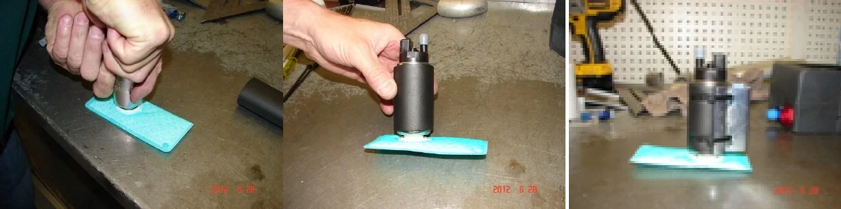
We need to find the center of the surge box on the blank side and drill 2 #7 (.201”) holes. The new fuel pump bracket uses 2 10-32 button head Allen screws to attach it to the surge box. We want to mount it in the center of the box, both top to bottom and left and right. “Speed Square” works well to scribe a centerline with. (I used silver sharpie to show up in the picture) You can use the scribe like a center punch in the plastic to mark the locations. The holes need to be 1.75” apart on the vertical axis. Vertically and horizontally centered.
If the upper return lip of the box is more than ½ “(this varies box to box) you will need to cut a fish mouth relief for clearance above the pump bracket. It’s easier to work with the new pump bracket. (I used a safety wire can as a template) Clean and debur pump bracket mounting holes and clearance cut.
Last, if you do not already attach your return fuel line as to fill the surge box. It’s a good Idea to drill ¼” in the right rear corner area of the surge box now as well so you can wire tie the return hose later.
If your surge box was using a -6 90 or 45 deg. fitting inside as a pick up, Remove and discard it from the bulk head fitting in the side of the surge box. Clean all debris out of the surge box, attach the -6 cap provided in the kit to the outside of the bulk head fitting and set the box aside.


4. Next lets assemble the pump, bracket and line:
The base filter sock has a one time barb fitting, lay it on the bench opening up and push the pump in to it. You can feel it push in and stop. It doesn’t take a lot of force.
The black foam sleeve goes on the body of the fuel pump to dampen the pump.
7. The electrical bulk head fitting should be located as high as possible on service plate. So it’s not constantly in liquid fuel.
On factory drilled service plates, remove the return line bulk head fitting and enlarge the hole to 7/8’s. On owner ford converted cars I’m not 100% sure of the return line placement. We are going to relocate the return line fitting down on the same side of the service plate. If the return line fitting was placed on the drivers left of the service plate. Adding the electrical fitting high on the drivers right side as in the pictures is all that’s needed.
Note: Before drilling, please lay the large electrical fitting washer in the proposed location on the back side of the service plate. We need to check for interference with the service plate gasket, you may need to adjust the location.
For the electrical fitting, enlarge or drill a 7/8” hole with a sharp uni-bit. It takes a heavy duty drill or drill press to do this. Turn the bit slow with even pressure; drill through with the 7/8’s step on the bit. Carefully debur the hole front and back.
For the new return line location, with the uni-bit drill to the 9/16’s step and flip the plate over to finish the hole. Used with care a sharp bit will chamfer the edge of the hole.
Note: Use care to not go deeper than the 9/16’s step, I marked the bit with a red marker.

8. Make sure the plastic sealing washer is on the outside of the electrical bulk head fitting on both fittings. Install the flat washer and nut with a little blue thread locker on the inside of both fittings. Tighten to at least 35 ft lbs. Tighten the body of the gland nut at this time as well.

9. Loosen the compression nut on the electrical fitting. Insert the fuel pump pig tail wires through the rubber grommet from the inside out. Leave about 12 to 14 inches of wire on the inside of the service plate. Cut to length on the outside, 10 to 12 inches will allow you to wire tie the connector body to the rear brake line above the front lower rear control arm mount. Tighten the gland nut a little more than hand tight; remember it is just compressing the rubber grommet on to the vinyl wire insulation.
Note: Take care not to tear or scratch the holes in the grommet. It’s a good idea to use a little lube on the vinyl wire insulation.

10. Terminate the pig tail with the male pin side of the connector. This is a bit tedious as the crimping procedure leaves little room for error. You will need a “B” style crimper, one that rolls the edges of the crimp area to the center on the bare wire and on the edge of the insulation as well. This is an OEM style crimp and can carry 8 to 10 amp load @12 volts. Failure to make tight crimps will cause voltage drop, heat and hurt pump performance.
Note: If in doubt, please read the “Molex MX 150 Manual” in the Technical section of the SCCA Enterprises web site.
Now the female pin connector body to the Roush EFI harness, trim wires to appropriate length.
Red to Green in pin location #1.
Black to Black in pin location #2,
Note: If the drilling service plate, termination and connector body assembly in above steps is beyond your comfort please consult your local CSR.
The service plate modifications are done set aside until final assembly.
11. Prepare the cell foam for surge box placement. If you were having good fuel pick up performance…I would install the surge box back in the same location with the pump to the rear of the car. If not, I like to install the Box about 1.5 inches from the back and left of the step in the cell. Location of the surge box in the cell is free. You need to make sure the surge box fits tightly in the foam. Use the large piece above the surge box to help pin it down. With added weight of the pump attached it’s likely for it to want to move around more than in the past. If you need to cut or trim the cell foam an electric carving knife works really well. It makes almost no foam debris. If you need new or extra foam to complete the installation please contact your CSR.
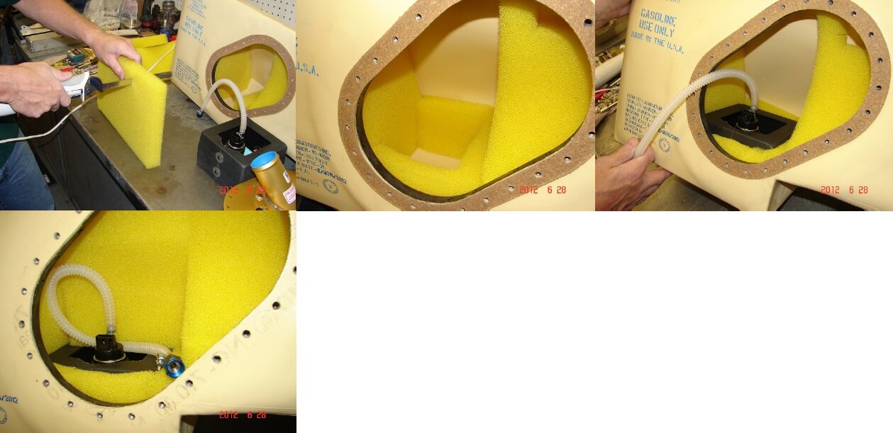
12. Place the new gasket on the cell and attach the fuel pump connector, feed and return lines.
Make sure the new hose is looped as in the picture, down and to the left along with the fuel pump pig tail. Make sure the return fuel line is lightly wire tied to the surge to return unused fuel back in the surge box. I’ve had very good luck picking up the last ½ to ¾ of a gal in this position.
Note: It’s very important to keep both line and wires away from the edge of the filler neck tubing. If left in contact over time the edge of the tubing would chafe the wires or new plastic fuel line.
13. The vent hose should be a 90 deg fitting with a piece of fuel line long enough to lay horizontal on the top surface of the cell. To the left or the right depends on the tracks in your area. This will minimize the over flow during the first few laps of a session on a full tank.
Tighten the service plate bolts in crisscross pattern to 35 in lbs. in 2 or 3 steps as not crush the new gasket under the first 2 or 3 bolts.
Once the cell is back in the car depending on how your lines were made you can use the -6 union provided in the kit to connect the old in and out pump lines or make a new line. If installed remove the in line pre filter and old fuel pump bracket.
At this time the “In fuel cell fuel pump kit” is not mandatory. Only contents of the kit as provided are approved and required to use the in fuel cell pump. This instruction sheet will be an update / alternate fuel system installation in the Roush Manual; which is referenced in the GCR.